Resistor Calculator
Calculate Engine Horsepower Fast and Accurately with Our Engine Horsepower Calculator
Table of Contents
- Introduction
- What Is a Resistor Calculator?
- How a Resistor Calculator Works
- Reading Resistor Color Codes with a Resistor Calculator
- Resistor Calculator for Series and Parallel Circuits
- Ohm’s Law and the Resistor Calculator
- Resistor Calculator for LED Current Limiting
- Tolerance and Power Rating – What Your Resistor Calculator Reveals
- Resistor Calculator for Voltage Divider Circuits
- Common Resistor Calculation Mistakes to Avoid
- Resistor Calculator for Students and Professionals
- FAQs
- Conclusion
Introduction
Resistors are among the most fundamental components in all of electronics — and correctly identifying, calculating, and applying them is a skill that every engineer, hobbyist, and student needs. Whether you are reading the color bands on a through-hole resistor, designing a voltage divider, limiting current to an LED, or calculating the combined resistance of a complex circuit, precision matters. A single wrong value can damage components, waste power, or cause a circuit to behave unpredictably. That is where a Resistor Calculator becomes essential.
A Resistor Calculator eliminates guesswork from electronics work by instantly converting resistor color codes into resistance values, calculating equivalent resistance in series and parallel configurations, and performing Ohm’s Law calculations — all in one fast, reliable tool. Instead of consulting datasheets, memorizing color code tables, or performing manual arithmetic that is easy to get wrong, you enter your inputs and get an accurate result in seconds.
This guide covers everything you need to know about the Resistor Calculator: how it decodes color bands, how it handles series and parallel resistance calculations, how it applies Ohm’s Law, and how to use it for practical applications like LED current limiting and voltage dividers. Whether you are a student building your first circuit, a hobbyist working on a DIY electronics project, or a professional engineer verifying component values, a Resistor Calculator is the tool that makes every calculation fast, accurate, and error-free.
What Is a Resistor Calculator?
A Resistor Calculator is a digital tool that performs resistance-related calculations for electronic circuits. It covers several distinct but related functions — color code decoding, series and parallel resistance calculation, Ohm’s Law solving, and application-specific calculations like LED resistor sizing and voltage divider design.
Resistance is measured in ohms (Ω) — the unit that quantifies how strongly a component opposes the flow of electrical current. A Resistor Calculator works with the full range of practical resistance values, from fractions of an ohm in low-resistance shunts to megaohms in high-impedance measurement circuits.
A Resistor Calculator is used by:
- Electronics students learning circuit theory and component identification
- Hobbyists building Arduino, Raspberry Pi, and DIY electronics projects
- PCB designers selecting correct resistor values for new circuit layouts
- Technicians identifying unmarked or unfamiliar resistors during repair
- Engineers verifying resistor network calculations during design review
- Educators demonstrating Ohm’s Law and circuit concepts in the classroom
The core value of a Resistor Calculator is accuracy and speed. Color code reading errors are among the most common mistakes in manual electronics work — and a wrong resistor value in the wrong place can destroy sensitive components or cause circuits to malfunction in ways that are difficult to diagnose. A Resistor Calculator removes human color-reading error entirely and handles all supporting calculations with mathematical precision.
How a Resistor Calculator Works
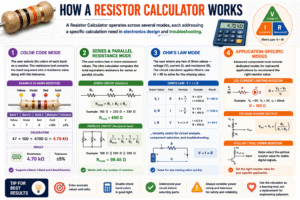
A Resistor Calculator operates across several modes, each addressing a specific calculation need in electronics design and troubleshooting.
Color Code Mode The user selects the colors of each band on a resistor — typically 4 bands (three value bands plus one tolerance band) or 5 bands (three significant digit bands, one multiplier band, and one tolerance band). The resistance tool converts the selected band sequence into a resistance value in ohms, kilohms, or megaohms along with the tolerance percentage.
Series and Parallel Resistance Mode The user enters two or more resistance values. The ohm calculator computes the total equivalent resistance for a series circuit (simple addition) or a parallel circuit (reciprocal sum formula) and displays the result.
Ohm’s Law Mode The user enters any two of three values — voltage (V), current (I), and resistance (R). The circuit calculator applies Ohm’s Law (V = IR) to solve for the missing third value, making it instantly useful for circuit analysis, component selection, and troubleshooting.
Application-Specific Modes Advanced component tool tools include dedicated modes for LED current limiting resistor sizing, voltage divider output calculation, and pull-up/pull-down resistor selection. These modes combine Ohm’s Law with application-specific formulas to produce a directly usable component value recommendation.
Reading Resistor Color Codes with a Resistor Calculator
The resistor color code is a system of colored bands printed on resistor bodies that encodes the resistance value and tolerance. It was standardized by the IEC (International Electrotechnical Commission) and has been used in electronic components for decades. A Resistor Calculator decodes this system instantly, eliminating the need to memorize or look up the color-to-digit mapping table.
The color code digit assignments are:
| Color | Digit | Multiplier |
|---|---|---|
| Black | 0 | ×1 |
| Brown | 1 | ×10 |
| Red | 2 | ×100 |
| Orange | 3 | ×1,000 |
| Yellow | 4 | ×10,000 |
| Green | 5 | ×100,000 |
| Blue | 6 | ×1,000,000 |
| Violet | 7 | ×10,000,000 |
| Gray | 8 | — |
| White | 9 | — |
| Gold | — | ×0.1 |
| Silver | — | ×0.01 |
Tolerance band colors:
- Gold: ±5%
- Silver: ±10%
- Brown: ±1%
- Red: ±2%
- Green: ±0.5%
- Blue: ±0.25%
A 4-band resistor example: Red – Violet – Orange – Gold = 2, 7, ×1,000, ±5% = 27,000Ω (27kΩ) ±5%
A 5-band resistor example: Brown – Black – Black – Red – Brown = 1, 0, 0, ×100, ±1% = 10,000Ω (10kΩ) ±1%
A Resistor Calculator decodes both 4-band and 5-band resistors in seconds, with no risk of misreading a color under poor lighting or confusing similar shades. This is particularly valuable for orange vs. red and blue vs. violet — color pairs that are routinely misread even by experienced technicians without a reference tool.
Resistor Calculator for Series and Parallel Circuits
One of the most frequently used functions of a Resistor Calculator is computing equivalent resistance for series and parallel resistor networks. Understanding which formula applies — and applying it correctly — is foundational to circuit design and analysis.
Series Resistance When resistors are connected end-to-end in a series circuit, the total resistance is simply the sum of all individual values:
R_total = R1 + R2 + R3 + … + Rn
Series resistance is straightforward, but errors in manual addition compound quickly when many resistors are involved. A electronics calculator handles any number of series resistors instantly and without arithmetic error.
Example: R1 = 470Ω, R2 = 1kΩ, R3 = 2.2kΩ R_total = 470 + 1,000 + 2,200 = 3,670Ω (3.67kΩ)
Parallel Resistance When resistors are connected side by side in a parallel circuit, the total resistance is always less than the smallest individual value. The formula is:
1/R_total = 1/R1 + 1/R2 + 1/R3 + … + 1/Rn
Or equivalently for two resistors:
R_total = (R1 × R2) ÷ (R1 + R2)
Parallel resistance calculations are where manual arithmetic becomes most error-prone, particularly when dealing with non-round values. A resistance tool applies the reciprocal sum formula with full precision, returning an exact result in a fraction of a second.
Example: R1 = 1kΩ, R2 = 1kΩ R_total = (1,000 × 1,000) ÷ (1,000 + 1,000) = 500Ω
Two equal resistors in parallel always produce exactly half the individual value — a useful sanity check when verifying ohm calculator results by hand.
Ohm’s Law and the Resistor Calculator
Ohm’s Law is the single most important relationship in basic electronics, and a Resistor Calculator that includes Ohm’s Law solving covers the full triangle of electrical quantities — voltage, current, and resistance — in one tool.
Ohm’s Law states:
V = I × R
Where:
- V = Voltage in volts (V)
- I = Current in amperes (A)
- R = Resistance in ohms (Ω)
A circuit calculator applies all three rearrangements of this formula:
- Voltage unknown: V = I × R
- Current unknown: I = V ÷ R
- Resistance unknown: R = V ÷ I
Practical Ohm’s Law examples using a component tool:
- A 5V supply powers a circuit drawing 20mA. Resistance = 5 ÷ 0.020 = 250Ω
- A 12V supply pushes current through a 470Ω resistor. Current = 12 ÷ 470 = 25.5mA
- A sensor requires exactly 10mA from a 3.3V supply. Resistance = 3.3 ÷ 0.010 = 330Ω
A electronics calculator that combines color code decoding with Ohm’s Law solving is particularly powerful — you can identify the value of a resistor from its color bands, then immediately calculate the current it will pass at a given voltage, all within the same tool.
Resistor Calculator for LED Current Limiting
One of the most common practical applications of a Resistor Calculator is sizing the current limiting resistor for an LED circuit. LEDs are current-driven devices — they do not regulate their own current draw and will pull excessive current and burn out if connected directly to a voltage source without a series resistor.
The formula for LED current limiting resistor calculation:
R = (Vs – Vf) ÷ If
Where:
- Vs = Supply voltage (e.g., 5V, 12V)
- Vf = LED forward voltage (typically 1.8–2.2V for red/yellow, 2.8–3.5V for blue/white/green)
- If = Desired LED forward current (typically 10–20mA for standard LEDs)
A resistance tool for LED sizing handles this formula automatically:
Example: 5V supply, red LED (Vf = 2.0V), desired current 15mA (0.015A)
R = (5 – 2.0) ÷ 0.015 = 3.0 ÷ 0.015 = 200Ω
Since 200Ω is not a standard resistor value, a ohm calculator will typically suggest the nearest standard E12 or E24 series value — in this case, 220Ω — which gives a slightly lower current of approximately 13.6mA, well within the safe operating range.
The power dissipated in the resistor should also be verified:
P = I² × R = (0.0136)² × 220 = 0.041W
A standard ¼W (0.25W) resistor is more than adequate for this application. A circuit calculator that includes power dissipation in its LED output prevents component failures from thermal overload — a concern that is easily overlooked when calculating by hand.
Tolerance and Power Rating – What Your component tool Reveals
Two properties beyond the nominal resistance value are critical to correct resistor selection: tolerance and power rating. A complete electronics calculator addresses both.
Tolerance Tolerance expresses how far the actual resistance of a manufactured resistor may deviate from its marked value. A 10kΩ resistor with ±5% tolerance may measure anywhere from 9,500Ω to 10,500Ω — a 1,000Ω spread on either side of nominal.
Common tolerance classes and their applications:
- ±5% (gold band): General-purpose circuits where precision is not critical
- ±1% (brown band): Precision circuits, instrumentation, and measurement applications
- ±0.1% and below: High-precision measurement, reference circuits, and calibration equipment
A resistance tool that decodes the tolerance band gives you an immediate picture of the actual resistance range — not just the nominal value — which is essential for circuits where component variation affects performance.
Power Rating The power rating of a resistor specifies the maximum continuous power it can dissipate as heat without damage. Common through-hole resistor power ratings are 1/8W, 1/4W, 1/2W, 1W, and 2W.
Power dissipation is calculated using:
P = V² ÷ R (when voltage is known) P = I² × R (when current is known)
Always select a resistor with a power rating at least twice the calculated dissipation to allow a safety margin and ensure long component life. A ohm calculator that includes power dissipation output eliminates the separate manual step of checking whether your chosen resistor can handle the thermal load of your circuit.
Resistor Calculator for Voltage Divider Circuits
A voltage divider is one of the most widely used resistor circuit configurations — used in sensor interfaces, analog signal conditioning, reference voltage generation, and countless other applications. A Resistor Calculator simplifies voltage divider design by solving for either the output voltage or the required resistor ratio.
The voltage divider formula:
Vout = Vin × (R2 ÷ (R1 + R2))
Where R1 is the upper resistor (connected to Vin) and R2 is the lower resistor (connected to ground).
Practical voltage divider examples using a circuit calculator:
- Scaling 12V to 3.3V for an ADC input: R1 = 27kΩ, R2 = 10kΩ
- Vout = 12 × (10,000 ÷ 37,000) = 3.24V ✓
- Generating a 2.5V reference from 5V: R1 = 10kΩ, R2 = 10kΩ
- Vout = 5 × (10,000 ÷ 20,000) = 2.5V ✓
A component tool for voltage dividers also calculates the current through the divider (I = Vin ÷ (R1 + R2)) and the power dissipated by each resistor — complete information needed to verify that the design is safe and practical before components are ordered.
Important considerations a electronics calculator helps you evaluate:
- Loading effect: A low-impedance load connected to Vout shifts the output voltage. Higher R1 and R2 values reduce quiescent current but increase sensitivity to loading.
- Impedance matching: For driving ADC inputs, voltage divider impedance should be low relative to the ADC input impedance.
Common Resistor Calculation Mistakes to Avoid
Even with a resistance tool, certain common errors can lead to incorrect component selection or circuit failure. Knowing these pitfalls ensures your calculations translate into reliable, working circuits.
Misidentifying Color Bands The most common manual error in electronics work — confusing orange with red, or blue with violet. Always use a ohm calculator to confirm color band readings rather than trusting naked-eye identification alone, especially under artificial lighting where color rendering is unreliable.
Using the Wrong Tolerance for Precision Applications Selecting a ±5% resistor for a precision circuit that requires ±1% accuracy will produce variable, unreliable results across production batches. A circuit calculator that displays the tolerance range — not just the nominal value — makes this mismatch immediately visible.
Ignoring Power Dissipation Connecting a ¼W resistor in an application that dissipates ½W will cause the resistor to overheat, drift in value, and eventually fail. Always run a power dissipation calculation in your component tool before finalizing component selection for any circuit carrying significant current.
Confusing Series and Parallel Configurations Applying the series formula to a parallel circuit — or vice versa — produces completely wrong resistance values. Confirm your circuit topology before selecting the calculation mode in your electronics calculator.
Forgetting to Convert Units Mixing ohms, kilohms, and megaohms without converting to consistent units produces arithmetic errors. A resistance tool handles unit conversion automatically, but if you are entering values manually, always confirm that all inputs use the same unit before reading the result.
Neglecting Standard Value Constraints Resistors are manufactured in standardized value series (E12, E24, E48, E96, E192). Your calculated ideal value may not exist as a standard part. A ohm calculator that includes nearest standard value suggestions saves the separate step of consulting an E-series table and prevents ordering errors.

circuit calculator for Students and Professionals
A component tool serves two very different audiences in electronics — students building foundational understanding, and professionals solving complex design challenges — and it delivers genuine value to both.
For Students Learning electronics means simultaneously absorbing color code conventions, Ohm’s Law relationships, series and parallel resistance behavior, and their practical applications. A electronics calculator used alongside coursework accelerates learning by providing immediate verification of manual calculations, clear numerical feedback that reinforces theoretical concepts, and a reliable reference during lab work and circuit building.
Students who use a resistance tool as a learning tool rather than just a shortcut develop better intuition for component values — because seeing correct answers instantly allows them to cross-check their own reasoning and identify where their thinking diverged from the correct approach.
For Professionals In professional PCB design, embedded systems development, and electronic product development, a ohm calculator is a productivity tool that eliminates low-value manual arithmetic from the design workflow. Engineers who use a circuit calculator consistently:
- Reduce component selection errors in schematic entry
- Speed up design reviews by having verified resistance calculations on hand
- Catch tolerance and power rating issues before prototype construction
- Verify rapid design changes without recalculating by hand under time pressure
For both audiences, a component tool is most valuable when used consistently — as a standard part of every circuit design session, not just when a calculation seems difficult. The errors it prevents are most often the ones that seem too simple to check — misread color bands, forgotten unit conversions, and overlooked power ratings.
FAQs
What is a Resistor Calculator used for? A Resistor Calculator is used to decode resistor color codes, calculate series and parallel resistance, apply Ohm’s Law to find voltage, current, or resistance, size LED current limiting resistors, design voltage dividers, and calculate power dissipation. It covers the full range of practical resistance calculations in electronics design and troubleshooting.
How do I read a resistor color code with a electronics calculator? Select the color of each band on your resistor in the color code mode of the resistance tool. For a 4-band resistor, select three value bands and one tolerance band. For a 5-band resistor, select three significant digit bands, one multiplier band, and one tolerance band. The tool instantly displays the resistance value and tolerance range.
What is the difference between a 4-band and 5-band resistor? A 4-band resistor encodes a two-digit value, while a 5-band resistor encodes a three-digit value for higher precision. A ohm calculator handles both formats — select the correct number of bands before entering your color selections to ensure the correct decoding formula is applied.
How does a circuit calculator calculate parallel resistance? A component tool applies the reciprocal sum formula: 1/R_total = 1/R1 + 1/R2 + … + 1/Rn. For two resistors, the simplified product-over-sum formula (R1 × R2) ÷ (R1 + R2) gives the same result. The tool handles any number of parallel resistors and returns the equivalent resistance with full precision.
Can a electronics calculator help me select the right resistor for an LED? Yes. A resistance tool in LED mode takes your supply voltage, LED forward voltage, and desired forward current as inputs, applies the formula R = (Vs – Vf) ÷ If, and returns the required resistance along with power dissipation and the nearest standard resistor value. This covers all the information needed for safe LED circuit design.
What power rating should I choose for my resistor? Use a ohm calculator to calculate the power dissipated by your resistor (P = V² ÷ R or P = I² × R). Always choose a resistor with a power rating at least twice the calculated dissipation — this provides a thermal safety margin that ensures long component life and prevents failure under slight overcurrent conditions.
Why does my circuit behave differently than the circuit calculator predicted? Common causes include resistor tolerance variation (the actual value may differ from nominal within the tolerance range), temperature effects on resistance, loading effects from other circuit elements connected to the same node, and contact resistance in connectors or breadboards. A component tool provides ideal calculated values — real-world circuits include these additional factors that affect measured performance.
Can a electronics calculator handle surface-mount (SMD) resistors? SMD resistors use a numerical marking code rather than color bands. A resistance tool designed for SMD components decodes 3-digit codes (e.g., 472 = 47 × 10² = 4,700Ω) and 4-digit codes (e.g., 1002 = 100 × 10² = 10,000Ω). Select the SMD mode in your ohm calculator to decode surface-mount component markings correctly.
Conclusion
A circuit calculator is one of the most essential tools in any electronics toolkit — for students learning circuit fundamentals, hobbyists building DIY projects, and professional engineers designing production hardware alike. It replaces error-prone manual color code reading, eliminates arithmetic mistakes in series and parallel calculations, and applies Ohm’s Law with instant, reliable precision.
The range of tasks a component tool handles covers virtually every resistance-related need in practical electronics work — from identifying a component pulled from a parts bin to designing a precision voltage divider to sizing an LED resistor for exactly the right brightness. Each calculation takes seconds and produces results that are mathematically guaranteed to be correct given accurate inputs.
Resistor errors are among the most common and most costly mistakes in electronics — they damage components, distort signals, waste power, and create diagnostic headaches that can take far longer to resolve than the original calculation would have taken. A electronics calculator eliminates these errors at the source, before a component is ever placed in a circuit.
Use a resistance tool for every resistor selection, every circuit analysis, and every component verification. The combination of color code decoding, resistance network calculation, Ohm’s Law solving, and application-specific formulas — delivered instantly by a reliable ohm calculator — is the foundation of accurate, efficient, and professional electronics work at every level of experience and complexity.